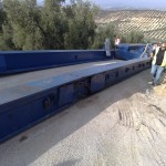
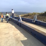
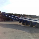
The main problem with turbine tower trailers is that they are very low.
For this reason we normally use long transition curves in vertical alignment, with a parameter of the parabola (Kv) of 400 or even more. This is the best approach, as for instance the alternative of a minimum length definition of the transition is not effective (the result will depend on the difference between entry and exit slope).
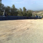
If shorter, more aggressive changes in vertical alignment are made (mainly at the end of a slope, when the horizontal crane pad is reached) there is the risk of having the trailer stuck as in the pictures below.
The height below the tower is just a few centimeters, so this is one of the critical points to check in a constructive project of a wind farm.
As a bonus I post also one of the incredible manoeuvres I’ve seen in the real word, a truck almost flying in a mountainous wind farm.
UPDATE 02/04/2020:
I have been asked to define more in detail how is defined the Kv parameter mentioned in the post.
I am referring to this formula:
L = Kv x (i% / 100)
Where:
L = Length of the parabola
i% = absolute value of difference between slopes (for instance, changing from 3% to -2% it would be 5%)
I think that in some road design software (like Civil 3D) you have to use the K value but multiply it by 100.
If you are unsure about the result I would recommend you to do a “full scale” test of the results.
You can do it plotting the resulting alignment at a 1:1 vertical / horizontal scale the alignment and after use an AutoCAD block representing the blade trailer. It will help you to see how many cm you have below the trailer in the lowest part.
This method is not 100% accurate (it does not consider the shock absorbers) but it is better than nothing.


Leave a Reply