One of the problems that occurs frequently to engineers working on wind farms is how to modify existing access roads to allow the transit of special vehicles.
I was contacted by several readers of the blog who had this issue – the last one was Egil from Norway who led me to write this article.
In general, the problem is usually a curve that is too tight, a change of slope that is too fast (i.e., a road crest in the vertical alignment where the change of slope is too sudden and the truck “hits” underneath) or a combination of the two.
I am describing in this post the procedure I have followed in the past. If you have followed different steps please drop me a line.
The example is taken from a project where the blade truck was hitting below (there is usually very little space under the trailer – as little as 20 centimeters).
The first step is to send a topographer to create a cartography as detailed as possible of the area.
Both GPS and “traditional” topography will be fine while I would avoid LIDAR because you would have too many points to work with. It is sufficient to work with a simplified model.
You will usually receive the results in AutoCAD DXF or a similar format, ready to use.
The next step is to create a tridimensional model of the existing road. I usually work with AutoCAD Civil 3D – however there are several similar software in the market.
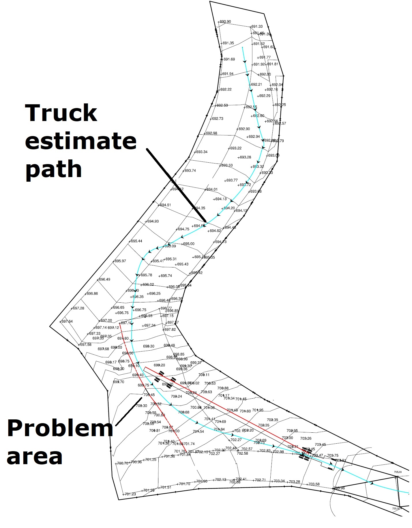
Then I use AutoTurn to calculate the path of the truck. I really like this software as it gives me a very reliable simulation of the wheel path and the swept path area.

The following step is to use Civil 3D (or your favourite software) to calculate longitudinal & cross sections (representing the ground “below the truck” and “as seen from the wheels”)
This help me deciding if and were changes to the existing roads are needed. You can see in the image below where the trailer is “touching” the road. In this example I was already aware of the problem as I was contacted by the colleagues on site.

The next step is to modify the geometry of the road “manually”.
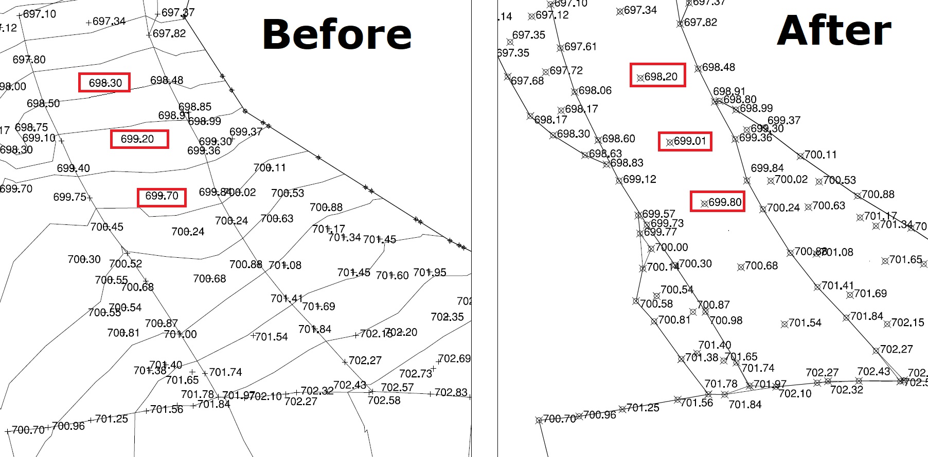
This is done changing the elevation of the points in the topography one by one in the area of the problem recalculating the longitudinal profile and the transversal sections until I reached a shape that looked OK in terms of torsion, slope and free space below the truck.

You can see in the image above marked in red the points that I have changed. At two points the ground has been lowered, at one point it has been raised.
When you are satisfied with the solution you can export all relevant information (digital elevation model, cross section, longitudinal profiles, etc.) and send it to the topographer on site so that the changes can be implemented.
In the case of bends, if only minor modifications are needed, the same procedure can be followed changing points as needed.
Leave a Reply